
Timing:
Some stage charts put them pretty early in the order, others put them later. I think it needs to happen at the same time the injectors are upgraded or at most a step before. Larger injectors equals more boost potential and upgraded intercoolers are neccessary to get the larger air volume as cool as the lesser stock air volume was before.
Special tools:
12mm Gear Wrench
Procedure:
1. Disconnect the negative terminal (1 x 10 mm) of the battery. Jack up the front of the car and place it on jackstands. Use a china marker to 'stripe' the facia/fender joint. This indexing will help get the joint aligned properly when putting the facia back on.
2. Remove the centerpanel (2 or 4 x 10 mm depending on year).
3. Remove the front black splash shielding (lot of screws & bolts & stuff. keep close track of what goes where). There's a couple bolts up high but are covered by the side splash shields. Remove all bolts along the bottom of each side splash shield.
4. Turn the front wheels all the way to the left. Remove the bolts in the passenger front wheel liner (4 x 10 mm) and bend it back/down (3.)
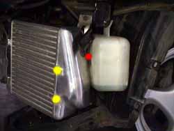
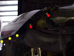
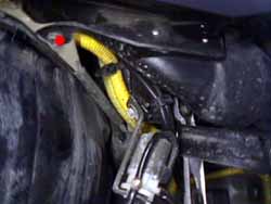
5. Remove the bolts holding the side of the facia to the fender (3 x 10mm) (yellow dots in 4.). Remove the bolt holding the metal facia backing to the brace (1 x 10mm).
6. Remove the corner lamps (2 x phillips). Disconnect the electricals.
7. Through the hole where the corner lamp was, remove the nuts holding the corner of the facia onto the fender (2 x 10 mm nuts) (red dots in 4.).
8. Repeat steps #4 - 7 for the driver side. Use a 10mm short socket on a swivel and extension to get to the bolt holding the metal facia backing to the brace (1 x 10mm).
9. Remove the bolts holding the facia to the bottom of the bumper (2 x 10 mm bolts) (5.). Remove the bolts holding the facia to the front of the frame (4 x 10 mm bolts) (6.). Hold the facia in place and then gently remove it. The brackets the bottom two bolts were run through might make it a bit challenging. Be extremely careful not to scratch the paint on the facia with the 4 studs sticking out from the fronts of the fenders.
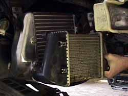
10. Remove the shrouds on the ICs (2 x 10 mm bolts & 2 x phillips plastic clips each side) (7.).
11. For the HKS (& Stillen?) ICs, the air intake ducts will need to be removed. Remove the bolt holding them in place (1 x 10 mm) on each side (8.). If a K&N type intake or something else besides the stock airbox isn't installed by now, it needs to be. Remove the ducts by pulling them straight out (9.)
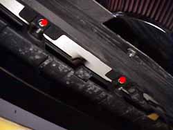
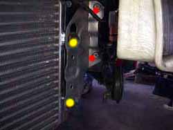
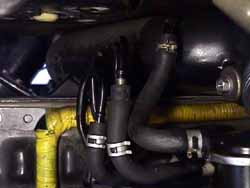
12. On the passenger side, loosen the clamps for the hoses coming in and out of the ICs (2 x 8 mm). Remove the IC by removing the single bolt from the backside & unbolting the mounting bracket from the frame on the front (3 x 12 mm bolts) (red dots in 10.).
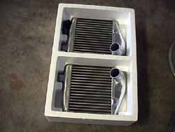
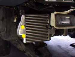
13. Remove the mounting bracket from the stock IC and bolt it onto the aftermarket IC tightening finger tight (2 x 12 mm bolts) (yellow dots in 10.). Fit the IC into the intake hoses and push it into place. Finger tighten the mounting bracket bolts back on the frame. Finger tighten the bolt to the back of the intercooler. Tighten all the bolts once everything is in place (5 x 12 mm bolts).
14. On the driver side, loosen the clamps for the hoses coming in and out of the ICs (2 x 8 mm). Remove the bolt holding the outside of the coolant overflow reservoir to the hanging bracket. This allows access to the rear mounting bolt for the IC. If a 12mm Gear Wrench is available, this will go quickly, otherwise just work with a regular wrench. Remove the IC by removing the single bolt from the backside (1 x 12 mm bolt) . Unbolt the mounting bracket from the frame on the front (2 x 12 mm bolts).
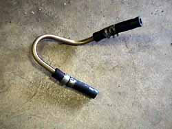
15a. If installing a 'taller' IC, on the driver side, remove the metal tubing loop from the intake tracting to the carbon canister and it's rubber couplings (11. & 12.). Bend the other 3 metal tubes upward to make room for the IC to fit in front of the carbon canister (13.). Supposedly this is easy to relocate. I examined it for a few minutes & decided it was easier to just bend the tubes up out of the way. Once all the metal loops are bent straight up and angled back a bit as they come to the outside of the car to match the angle of the IC, take some extra 1/4" vacuum line and conntect it to the intake tracting with a clamp, then loop it around and cut it off at the carbon canister nipple. Attach it to the carbon canister and clamp it too.
15b. I'm not sure how to deal with the 'thicker' ICs in this situation. The HKSs are right up against the carbon canister and the coolant overflow reservoir. They have to be thicker coming forward, not backward since there's no room. The tubes on the carbon canister shouldn't be a problem.
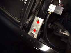
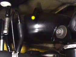
16. Remove the mounting bracket from the stock IC and bolt it onto the aftermarket IC tightening finger tight (2 x 12 mm bolts). Fit the IC into the intake hoses and push it into place. Finger tighten the mounting bracket bolts back on the frame. Finger tighten the bolt to the back of the intercooler. Tighten all the bolts once everything is in place (5 x 12 mm bolts). The rear mount bolt is easily done with a Gear Wrench (red dot in 15.). There are no toque specs for any of the mounting bolts. I'd recommend 9-12 ft-lbs. Reattach the coolant overflow reservior to the bracket ( 1 x 10 mm bolt).
17. If installing a 'taller' IC, either the original shrouds can be put back on, effectively wasting the extra surface area, or left off & have the air spill around it. I'd opt for the spill around option. There are sets of modified shrouds being made to fit the taller ICs. I'm going to mod a set myself & put the info in here when I do. If it's a 'thicker' IC, like the GReddy, then just put the shroud back on. Either way, make *sure* the holes on the endcaps are filled with the bolts.. otherwise there will be a huge boost leak in the pressurized section of the intake tracting (yellow dots in 14. & 15.).
18. Reinstall the front facia in reverse order of it's removal. There are no torque specs for any of the front bolts. I'd recommend 9-12 ft-lbs on anything with real machined threads.
Published 2-16-01
© Twin Turbo Zs of Dallas - All Rights Reserved 2001
2.
3.
4.
5.
6.
7.
8.
9.
10.
11.
12.
13.
14.
15.