
Timing:
There has been some discussion about what the maintenance interval should be for changing the timing belt. The earlier Z service manuals recommend every 60k miles or 48 months. The later ones suggest the NA can go as far as 105k miles before replacing the belt. From what I've learned it was a misprint, that's actually the distance in km, not miles. The VG30DE(TT) engine is low tolerance. In other words, if the belt slips or is installed improperly, there is a strong possibility the valves will hit the tops of the pistons. Something expensive to repair, but easily avoided if this maintenance is completed when it's supposed to be, either based on miles or time. I've had people e-mail me and say 'I had X miles on my timing belt & it looks just fine', while this is true (I've got 20+ hanging on my wall as trophies, they all look 'OK'), I've had a couple unfortunate people mail me & say 'I had X miles on my timing belt & it looked fine, except the break in the middle'.
Please read through this entire procedure before even buying the parts to do it. It's very easy to get stuck in a position of no return. I've written the article where if followed in the order listed, this is minimized. There are a few situations (the crank sprocket) where the proper tools make life simple, just be aware of the potential difficulties I list in doing this procedure. There's also some notes for air wrench users to speed things up. Some of the picture's contents don't match the actual order of the steps. I've made several revisions to the order since the pics were taken, etc.
Part Numbers:
- Timing Belt:
- NA
- 2/89-7/92 13028-16V00
7/92+ 13028-45P00 or 13028-45P86
- 7/89-4/93 13028-16V00
4/93+ 13028-45P00 or 13028-45P86
- 13070-45V04
- 9/91-9/93 California Auto TT 21200-42L05
all others 21200-42L00
- 14055-F6511
- 21010-22P26 or 22P27
- 21014-V5001AS
- TT A172M-67A0MVW
NA A172M-V530MVW
- A192M-F650AVW
- TT
- 7/89-9/93 A192M-42L0AVW
9/93+ A195M-F650AVW
- NA
- A195M-F650AVW
- 13042-16V00
- 2/89-9/93 13042-16V00
9/93+ 13042-10Y00
- 7/89-9/93 01001-00191
9/93+ 13037-75T00
- 13072-45V20
- 13021-16V10
- 13022-45V00 (Nissan's computers have the wrong part number listed,
this is correct)
Special Tools:
An assistant (not necessary, but makes things much simpler)
Pulley puller
Seal puller (not necessary)
Thin Lexan Plastic (see step 36)
5 mm hex head socket
6 mm hex head socket
White paint pen
Plastic faced mallet
Pry bar
Air impact wrench and impact sockets (makes certain steps much simpler)
27 mm socket
Other items:
Permatex Blue silicone gasket maker
2 gallons of distilled (pure, not spring) water
1 gallon of antifreeze
Optional bottle of Redline Water Wetter
Optional underdrive pulley & smaller
belts
I highly recommend getting a set of Mechanix
gloves
Procedure:
1. Disconnect the negative terminal on the battery.
2. Raise the front of the car & put it on ramps or jack stands, observe all safety precessions.
NOTE: For more detailed instruction on removing the accessory drive belts and crank pulley, read through the Underdrive Pulley Install page.
3. Remove the lower engine shield (6 x 10 mm)
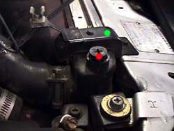
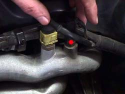
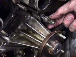
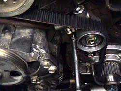
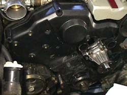
4. Open radiator petcock & drain fluid into a bucket (be VERY careful not to scald yourself if the car is warm). Once fluid is draining out into the bucket, open the radiator cap and remove the secondary fill plug (red dot in 1.) on the opposite side of the radiator. Let the radiator drain completely.
5. Remove the lower fan shroud from the upper fan shroud and radiator (3 clips). Remove the lower radiator hose bracket (1 x 10 mm).
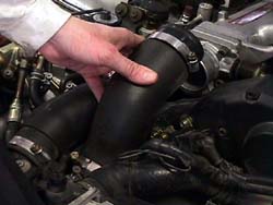
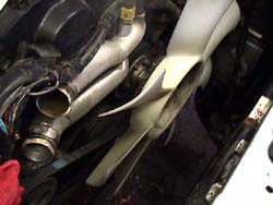
6. On turbos, remove the left and right throttle body intake hoses (2.). Put rags into each of the intercooler tubes at the front to keep anything from falling into there (4 hose clamps x 8 mm).
7. Remove the upper radiator brackets (2 x 10 mm) (green dot in 1.).
8. On '93 & earlier Zs, remove the recall power transistor wire wraps (3.) from the upper radiator hoses.
9. Remove the upper radiator hose. (2 hose clamps x 10 mm). Disconnect the lower radiator hose from the radiator, let it drain into the bucket. Disconnect the lower radiator hose from the engine. Remove the lower radiator hose. Disconnect the coolant overflow tube from the radiator (1 hose clamp). Check that it's off the radiator shroud down the driver's side. There's a spot it 'tucks' into to hold it in place about halfway down. Make sure the hose isn't allowed to drain, it will empty the overflow reservoir. I generally loop it around a hose on the driver side to keep it from falling down and draining. There are transmission fluid cooler hoses going into the radiator on the driver side on the automatic transmission models. Disconnect them where they come up to the lower radiator hose under the engine and let the contents drain into the bucket.
10. Remove the lower fan shroud (3 x clips). Remove the radiator. On turbos, the intercooler tubes will be in the way, wiggle the radiator around some to get it clear of them. Don't loose the two round rubber mounting grommets on the bottom of the radiator (4.).
11. Remove the fan from the fan clutch (4 x 10 mm). Remove fan clutch assembly from the water pump (4 x 10 mm).
12. Loosen the AC idler pulley (1 x 14 mm) and the adjustment bolt (1 x 12 mm).
13. Loosen the locking bolt (1 x 12 mm), the adjustment bolt (1 x 12 mm) & the pivot bolt (1 x 17 mm) on the alternator. Remove the bolt holding the adjustment bracket to the block, pull the bracket away from the block (1 x 12 mm).
14. Loosen the locking nut (1 x 12), the adjustment bolt (1 x 12 mm) & the pivot bolt (1 x 14 mm through the pulley's hole) on the power steering pump.
15. Remove all the accessory drive belts.
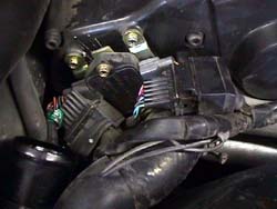
16. Unbolt the top & bottom bolt (2 x 8 mm) on the power transistor bracket, removing the entire assembly. Unplug the engine temperature sensor (yellow w/ the wire clip) & the thermal sensor (black spade plug) (red dot in 7.). Unscrew the bracket holding the harness under the crank angle sensor. On '90-'93s Pull back the rubber shield on the crank angle sensor plug (8.) & carefully remove the connector (another wire clip) or on the '94+, just unplug it. Bend the entire front engine wiring harness back out of the way.
17. Remove the plastic upper right timing belt cover (3 x phillips/8 mm, 5 x 5 mm hex head) (9.). Try to keep the screws in the appropriate holes. There are a lot of different lengths of bolt and they get easily confused if removed. There's one phillips/8 mm in the lower center of both plastic covers that should be unscrewed last. It's going into a spacer stud behind it and most of the time it backs the stud out instead of leaving the stud there.
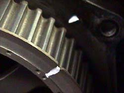
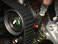
18. Turn the crank clockwise using the crank bolt until the dots on the exposed sprockets line up with the dots on the back covers (painted white for illustration purposes (10 & 11.). This places the engine's rotation at #1 Top Dead Center (TDC). Don't expect the belt's marks to line up, only the dots on the sprocket and the back cover. Rotate the crank about 10 degrees BeforeTDC (BTDC) (counter clockwise). This makes installing the belt easier later on.
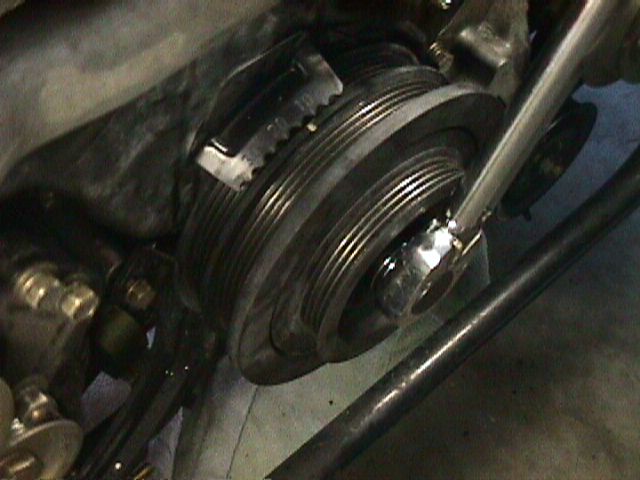
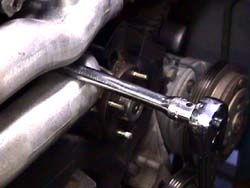
19a. For 5spds, put the car in 5th gear, make sure the parking brake is engaged. Loosen the crank pulley bolt (1 x 27 mm) (5.). Make sure to use a real penetrating lubricant beforehand. I recommend Blaster brand. An air wrench makes this much easier.
19b. For autos, if an air wrench is available, try it first to loosen the crank bolt (1 x 27 mm). Make sure to use a real penetrating lubricant beforehand. I recommend Blaster brand. If the air wrench alone doesn't work, or isn't available, here's the alternate method: NOTE: I don't have pics of this step specifically yet. Use the belt wrapping technique used later on the cam sprockets here. Basically wrap the rear set of grooves on the pulley with the old AC belt and loop the excess over to the bracket of the alternator (it loops around behind the adjustment bolt) to hold the pulley still. Doing this WILL ruin the belt, so make sure it's not going to be re-used.
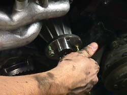
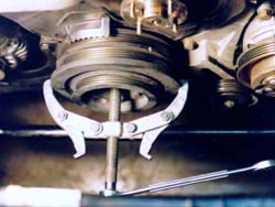
20. Once the crank bolt is broken loose, loosen it about 1/2" to give the pulley some room to move forward with the bolt still in the threads. Mount the pulley puller on the crank pulley, using the dimple in the head of the crank bolt as the contact point for the puller's center bolt. Clamp the arms on the THICK part of the pulley, not the very front (6.). The pulley is made of soft iron an will break easily if the front lip is used as the arm's contact points. Remove the crank pulley. Be careful with the woodruff key exposed on the crankshaft. Also be extremely careful with the AC condensor (the other radiator looking thing now exposed), it's rather fragile & a a good dent might cause it to leak out all the freon. Not good at all.
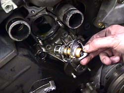
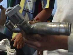
21. Move the coolant bucket to front center under the engine. Remove the water inlet tube (lower aluminum tube) (2 x 12 mm nuts, 1 X 6 mm hex head) (12.). Use a screwdriver to remove the thermostat (13.). Be careful not to scratch the mating surfaces.
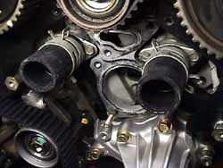
22. Squeeze the clamps on the water outlet tubes (red dots 14.), push them back onto the rubber hoses. Remove the water outlet tube (3 x 6 mm hex head). Remove all 4 clamps, remove both short water hoses.
23. Remove the plastic upper left timing belt cover (2 x phillips/8 mm, 5 x 5 mm hex head). Remember the one phillips/8 mm that's going into the spacer stud. Try to keep the screws in the appropriate holes. There are a lot of different lengths of bolt and they get easily confused if removed. Remove the metal lower timing belt cover (6 x 8 mm). If the spacer studs didn't come off with the plastic timing belt covers, remove them now (2 x 17 mm bolts)
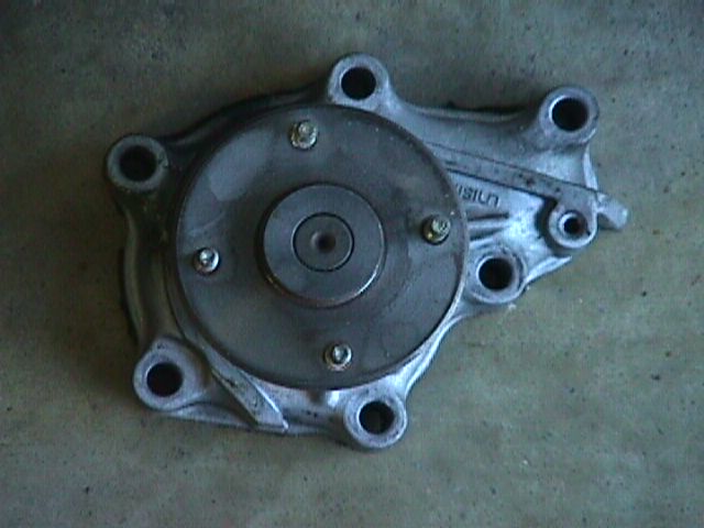
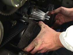
24. Remove the water pump (6 x 12mm) (15.). Clean off all the coolant fittings with a putty knife to ensure a good seal when replacing the parts. Be careful not to scratch the mating surfaces while cleaning off the old sealer. A small wire brush will quickly remove old sealer without damaging the mating surfaces.
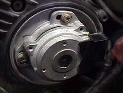
25. Remove the Crank angle sensor mounting bracket ( 3 x 12 mm) and crank angle sensor (16.).
26. Loosen the exhaust cam sprocket bolts (8 x 11 mm) (17.).
27. Remove the intake cam sprocket front covers (8 x 7 mm) (18.) there is a spring & O-ring behind the cover for the Variable Valve Timing on the '90-'95s, don't drop them. A small amount of oil will leak out from the inside of the sprocket, this is normal.
28. Jeff's auto-tensioner was almost at full extension (20.). Take one of the 10 mm bolts from the fan and screw it into the retention hole on the tensioner (red dot in 28.). When it's slowly tightened, it will be long enough to remove the tension from the belt. Remove the belt auto-tensioner (2 x 12 mm bolts, 1 x 12 mm nut). Loosen the nut first , then remove the bolt to the left, then the bolt to the right. Remove the timing belt. Use the old belt to wrap around each sprocket to control them while letting them come to rest. The cams will want to rotate a few degrees rather violently, try to avoid this because the VG30DE(TT) engine is low tolerance & the valves can make contact with the pistons under certain conditions. Always be careful around the cam sprockets when the timing belt is not on them and under tension. The cam lobes will want to relieve spring tension whenever possible. When the sprockets turn, the valves are coming to 'rest' in their seats. It's actually a good thing most of the time. The passenger side cams will definitely rotate. The drivers side cams are already settled.
NOTE: Here's a simple way I use to hold the intake sprockets in place while removing or tightening the bolts holding them in place.
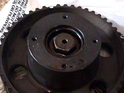
29. Remove the intake cam sprockets (2 x 19 mm) (20.). The intake cam sprockets changed in '94, the newer ones are silver and beefier looking (FWIW they are also adjustable). The ones shown here are '91. Use the belt wrap technique in the note above to hold them in place.
30. Remove the exhaust cam sprockets (8 x 11 mm) (17.).
31. Remove the upper middle idler pulley (1 x 14 mm).
32. Remove the back metal covers to access the cam seals (8 x 10 mm). There might be a stud on the either side to remove if it didn't come off with the plastic cover.
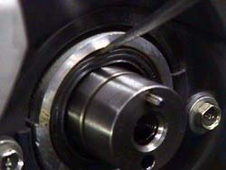
33. Remove the seals by carefully bending the outside ring with a punch or screwdriver (21.). DO NOT scratch the camshaft or outer sealing surface. Just barely dent the seal enough to get a screwdriver over the top & be able to pry down a little bit to pop it out. I can not stress enough how important it is to NOT scratch any of the mating surfaces. Scratching the cam will lead to VERY EXPENSIVE repairs because the seal will leak oil out into the timing belt area. Not something I care to think about. If a seal puller is available, it can be used on the intake cam seals, they don't seal to the camshafts, so the puller can be inserted and used.
34. Carefully clean the cam shaft & head mating surfaces with a rag. Lightly oil the new seal with motor oil inside & out. Slip the new cam seal over the end of the camshaft with the 'solid' side facing outward. Gently push the seal into place, then use one of the old seals (cleaned) as a spacer to tap the new seal in place using ONLY a plastic face mallet to avoid scratching/damaging the camshaft (22.).
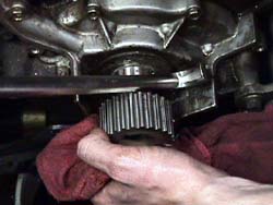
35. Use a pry bar to slide the crank sprocket & washer off the crank (23.). Be careful with the woodruff keys exposed on the crankshaft. If the sprocket doesn't come off, the simplest solution is to just cut it off. This is where the new crank sprocket and rear washer come into play. I don't waste time trying to heat it up etc. Striking it with a metal hammer is not a good idea either as the sprocket's metal is very soft and the teeth on the sprocket will become flat without much effort. With the gear at top dead center, cut through the gear over the key way with a 4" air cut-off wheel. Just slice across it being careful to not nick the crank or cut into the aluminum oil pump assembly behind it (too badly at least). Once a sufficient slot is cut, hammer a chisel into the slot. The sprocket will eventually crack over the keyway and then it will easily slide off.
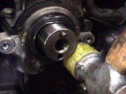
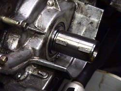
36. Remove the front main seal the same way as the cam seals (24.). Replacing the main seal is MUCH more difficult then the cam seals because of the shape of the crankshaft itself. There is a step the seal must get over to start to seat. All of the front seals have a tiny tension spring inside the seal, this spring doesn't stay seated very well while installing the seal. There is an easy way to do it with an additional 'tool' and a harder way to do it without.
Easy way: Get some thin Lexan plastic, cut a 4.5" x 3" rectangle out of it. Oil up the seal inside and out, then roll it up and slip it into the seal. Take this and slip it all over the crank and push it up into the seal's seat. The idea is to use it as a ramp over the step on the crank & into position without rolling over the seal and letting the spring in the seal loose. Use another old seal and slip it over the plastic and use it as a spacer to tap the new seal in place. once everything is seated, pull the old seal off the plastic, then gently pull the plastic out of there. If everything is lubed up, it should slip right out, leaving the seal perfectly seated and the spring on the inside remaining on the inside. Genius idea from Jim Gahl! I've used it several times now. Just make sure the seal is going in with the 'solid' side facing forward like the others.Seat the crank seal the same way the cam seals were seated. Run a finger all the way around the seal to make sure it is seated evenly, the bottom of the seal can't be seen without an inspection mirror.Harder way: I slip the seal up to the step with the 'solid' side facing outward & then pushed the bottom part into the seat. The seal is then at about a 45 degree angle with the top leaning out. I them put both of my thumbs on the bottom center of the seal and worked my thumbs around the edges keeping tension on the seal to up it upward as the seal started to seat, watching to make sure the spring doesn't come out of the seal. The technique is to maintain tension as the seal is worked in place, so the spring stays in place because the back part of the seal is NOT being allowed to roll over as it makes contact with the step on the crank. Very poor engineering on Nissan's part for maintenance purposes. All Nissan needed to do was taper the step off a bit and life would be OK. Be VERY patient here. After the rear lip of the seal is over the step, use an old seal to help tap the new on in place, starting from the bottom & finally working the way to the top.
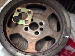
37. Install the washer & the crank sprocket over the woodruff keys on the crank shaft. The flat washer goes on the back side of the sprocket. If the lower belt cover loops around the crank, then a second flat washer goes on the front of the sprocket. If the lower belt cover doesn't loop around the crank, the bevel edged washer goes on the front with the bevel facing the rear to make the belt fall back onto the sprocket if it were to come forward.
38. Install the metal back covers (8 x 10 mm).
39. Clean off the ends of the intake cams. Install the exhaust cam sprockets (8 x 11 mm). The sprockets are self keying on the metal dowel pins. Just hand tighten the bolts for now.
40. Install the intake cam sprockets (2 x 19 mm), they are self keying too. Use the wrap technique. Torque to 90-98 ft-lbs (for '90-'95, not sure how/what the '96s look like)
41. Install the intake cam sprocket front covers. Make sure the O-rings are seated in the groove on the back of the cover & the spring is seated in the middle. Tighten the bolts (8 x 7 mm) to 1.1-1.8 ft-lbs.
42. Install the upper middle idler pulley (1 x 14). Torque to 32-43 ft-lbs.
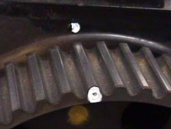
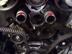
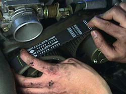
43. The arrow on the new timing belt will point to the front of the car. There are 5 marks on the outside of the new timing belt. 4 are close together, locate these & position them across the tops of the sprockets with the 4th mark to the passenger side exhaust cam sprocket (25.). This positions the 5th mark on the correct side of the crank sprocket at #1 TDC.
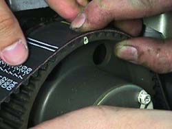
44. Start positioning the belt marks on the appropriate sprocket teeth beginning with the crank sprocket. Stick a screwdriver/pry bar between the belt & the oil pump shielding to hold the belt in place. Pull the belt and line the marks on the exhaust cam sprocket up on the driver's side, then the intake cam sprocket next to it & so on (we're 1 tooth off in 26.). If the sprockets are not close to the right area to land the marks on, wrap the old timing belt around the sprocket and rotate it until it's close enough to 'capture' under the mark. The dots on the back metal covers are for reference only at this point, same with the notch in the oil pump. All 15 indications will never line up perfectly. The only thing that matters are the lines on the belt and the marks on the sprockets lining up properly.
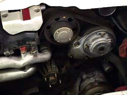
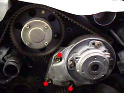
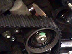
45. Install the new auto-tensioner on the stud & get the washers/nut started (1 x 12 mm). Have the helper push the auto-tensioner in place with a pry bar against the back of the auto-tensioner and the power steering pump bracket until the other bolts can be started (2 x 12 mm) The right one will be first, the left one second. (27.). Torque all to 12-15 ft-lbs.
46. Remove the 10 mm retaining bolt on the new auto-tensioner (inside edge, gold color w/ white paint on it) (red dot in 28.) to let the idler pulley arm push against the belt.
47. Shift the transmission to neutral. Put the crank bolt back in (make sure the thick washer is on it) & rotate the crank 2 times (720 degrees) clockwise to ensure the valves will not make contact with the pistons when the engine is started. Check the auto-tensioner's extension. It should be at about 4 mm. If it's not, put the retention bolt back in the auto-tensioner to remove tension on the belt. Slowly tighten the retaining bolt to relieve tension. If the retaining bolt is tightened too quickly, the casting on the tensioner will break. If it does, it's not a deal breaker. Just maintain tension on the belt and pry the backside of it instead of using the retaining bolt to retract the pulley. Loosen the two bolts and nut on the auto-tensioner, re adjust the position of the tensioner, tighten the bolts and nut again. Torque all to 12-15 ft-lbs. Release the retention bolt and go back to the start of this step. Repeat until the tension is correct.
48. Torque the exhaust cam sprocket bolts to 10-14 ft-lbs. in a criss-cross pattern.
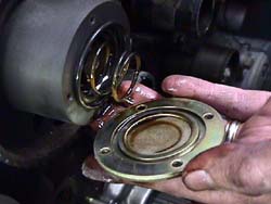
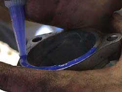
49. Put Permatex Blue on the mating surface of the water pump (29.) & install or use the gasket (6 x 12 mm, the 'stud' goes in the furthest right hole 13.). Torque to 12-15 ft-lbs. I didn't know the gasket existed until speaking with Steve Richardson of Courtesy Nissan while getting the part numbers for everything.
50. Install bottom metal cover (6 x 8 mm, the shortest bolt goes in the top hole on the right side) (30.). There's a bracket on the lower right side that's difficult to get around to get the cover in place.
51. Install the plastic upper left timing belt cover (2 x phillips/8 mm, 5 x 5 mm hex head, the lower middle is shorter bolt) (31.). If the spacer studs came out with either plastic cover, be aware they need to be the first bolt tightened. If they had to be removed to get the back covers off, put them back now (2 x 17 mm) and torque to 12-15 ft-lbs.
52. Install the crank angle sensor (3 x 12 mm) and torque to 12-15 ft-lbs. There is a key inside the shaft to align it properly with the cam shaft splines, make sure everything lines up properly. Install the plastic upper right timing belt cover (3 x phillips/8 mm, 5 x 5 mm hex head).
53. Install the two new short rubber water outlet hoses. Clamp the rubber hoses, making sure the left front one it pointing down & the right front one is pointing to the bottom-right. The rears can both face upward (32.). Put Permatex Blue on the mating surface of the water outlet tube & install (4 x 6 mm hex head) (33.). Torque to 12-15 ft-lbs. Re-clamp the rubber hoses, making sure the left front one is pointing down & the right front one is pointing to the bottom-right still.
54. Install the new thermostat, making sure the top indication on the thermostat is the top. Put Permatex Blue on the mating surface of the water inlet tube (34.) & install (2 X 12 mm nuts & 1 X 6 mm hex head). Torque to 12-14 ft-lbs.
55a. For 5spds, put the transmission into 5th gear. Remove the crank bolt (1 x 27 mm). Install the pulley (optionally the underdrive pulley). Torque to 159-174 ft-lbs.
55b. For autos, remove the crank bolt (1 x 27 mm). Wrap the pulley in reverse fashion as was probably required to loosen the crank bolt. Install the pulley (optionally the underdrive pulley). Torque to 159-174 ft-lbs.
56. Jam-nut the water pump studs in place (35.): Hand screw in the stud (short end goes into the pump). Thread on 1 10 mm nut, thread on a second one after it. Use two 10 mm wrenches (or wrench & socket) to tighten the nuts against each other. Tighten the stud into the hub like a bolt until it seats (about 4-6 ft-lbs). Use the two wrenches to break the nuts away from each other, making sure the stud stays in place. Remove both nuts & repeat for the other 3 studs.
57. Bring the front electrical harness across the front of the engine. Plug the crank angle sensor, thermal sensor, temperature sensor back in, bolt the power transistor back to the bracket (2 x 8 mm).
58. Put the water pump pulley on the pump hub. Re-attach the alternator adjustment bracket (1 x 12 mm). Torque to 16-22 ft-lbs. Install the new drive belts. The longest goes over the waterpump and alternator, the middle size goes around the AC compressor. The shortest goes over the power steering pump.
59. Install the fan and fan clutch (8 x 10 mm). Torque to 4.3-7.2 ft-lbs.
60. Tighten drive belts to appropriate specs, or 1/4" deflection at the midpoints except the power steering belt which is closer to 1/2" under a 22 lb. load.
61. Torque the AC idler pulley (1 x 14 mm) to 23 ft-lbs.
62. Torque the alternator locking bolt (1 x 12 mm) to 20-25 ft-lbs. Torque the alternator pivot bolt (1 x 17 mm) to 12-15 ft-lbs.
63. Torque the power steering pump locking nut (1 x 12 mm) to 20-25 ft-lbs.
64. Install the radiator. Make sure the radiator is seated properly in the lower mounting grommets. On the automatic models, plug the transmission cooler lines back in and tighten them (2 hose clamps x 10 mm).
65. Connect the negative cable to the battery (be ready with alarm buttons). Put the transmission in neutral. Make sure the parking brake is on. Start the engine to check the belt tension (especially if an underdrive pulley was installed). Don't let the engine run for too long without coolant. Make necessary adjustments.
66. Install the upper radiator brackets (2 x 10 mm). install the lower radiator shroud (3 x clips). Install the lower radiator hose (2 hose clamps x 10 mm). Install the upper radiator hose (2 hose clamps x 10 mm). Install the lower radiator hose bracket (1 x 10 mm). Replace the wire wraps on the power transistor wires. Connect the coolant overflow tube (1 x hose clamp).
67. On turbos, remove the rags from each intercooler tube & install the two throttle body intake hoses (4 hose clamps x 8 mm).
68. Fill the radiator with 1/2-2/3 gallon of antifreeze (and optional 1/2 bottle of Redline's Water Wetter) & then start filling with distilled (pure, not 'spring' or 'drinking') water. Once the radiator is full, start the car & let it idle. Turn on the air conditioner. Keep filling the radiator as required. After the temperature gauge reaches operating temperature plus a couple minutes the radiator should be full. Screw in the secondary fill plug. Cap the radiator. Check the coolant level in the overflow reservoir.
69. Check for coolant leaks on the radiator & hose clamps. Tighten where it leaks if necessary.
70. Install the lower engine shielding (6 x 10 mm).
71. Return the car to the ground. When making the first drive, keep an eye on the temperature gauge. If it starts to overheat, turn on the heater full blast to bring the tenmp down. Wait for the car to cool off & fill the radiator with more water.
REV: 11-3-03
DamonZ
Russell "Silky Smooth" Siebert
© Twin Turbo Zs of
Dallas - All Rights Reserved 1997-2003
1.
2.
3.
4.
5.
6.
7.
8.
9.
10.
11.
12.
13.
14.
15.
16.
17.
18.
19.
20.
21.
22.
23.
24.
25.
26.
27.
28.
29.
30.
31.
32.
33.
34.
35.